■ USB 2.0 USB IF Hi-Speed certified (TID # 40460272)
■ Single-chip integrated USB 2.0 transceiver, smart SIE, and
enhanced 8051 microprocessor
■ Fit-, form-, and function-compatible with the FX2
❐ Pin-compatible0
❐ Object-code-compatible
❐ Functionally compatible (FX2LP is a superset)
■ Ultra-low power: ICC no more than 85 mA in any mode
❐ Ideal for bus- and battery-powered applications
■ Software: 8051 code runs from:
❐ Internal RAM, which is downloaded through USB
❐ Internal RAM, which is loaded from EEPROM
❐ External memory device (128-pin package)
■ 16 KB of on-chip code/data RAM
■ Four programmable BULK, INTERRUPT, and
ISOCHRONOUS endpoints
❐ Buffering options: Double, triple, and quad
■ Additional programmable (BULK/INTERRUPT) 64-byte
endpoint
■ 8-bit or 16-bit external data interface
■ Smart media standard ECC generation
■ GPIF™ (general programmable interface)
❐ Enables direct connection to most parallel interfaces
❐ Programmable waveform descriptors and configuration
registers to define waveforms
❐ Supports multiple ready (RDY) inputs and control (CTL)
outputs
■ Integrated, industry-standard, enhanced 8051
❐ 48-MHz, 24-MHz, or 12-MHz CPU operation
❐ Four clocks per instruction cycle
❐ Two USARTs
❐ Three counter/timers
❐ Expanded interrupt system
❐ Two data pointers
■ 3.3-V operation with 5-V tolerant inputs
■ Vectored USB interrupts and GPIF/FIFO interrupts
■ Separate data buffers for the setup and data portions of a
CONTROL transfer
■ Integrated I2C controller; runs at 100 or 400 kHz
■ Four integrated FIFOs
❐ Integrated glue logic and FIFOs lower system cost
❐ Automatic conversion to and from 16-bit buses
❐ Master or slave operation
❐ Uses external clock or asynchronous strobes
❐ Easy interface to ASIC and DSP ICs
■ Available in commercial and industrial temperature grades
(all packages except VFBGA)
Features (CY7C68013A/14A only)
■ CY7C68014A: Ideal for battery-powered applications
❐ Suspend current: 100 A (typ)
■ CY7C68013A: Ideal for nonbattery-powered applications
❐ Suspend current: 300 A (typ)
■ Available in five Pb-free packages with up to 40 GPIOs
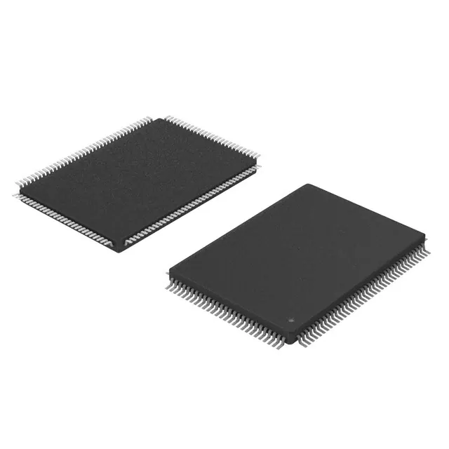
❐ 128-pin TQFP (40 GPIOs)
■ Two more GPIOs than CY7C68013A enabling additional
features in the same footprint
Applications
■ Portable video recorder
■ MPEG/TV conversion
■ DSL modems
■ ATA interface
■ Memory card readers
■ Legacy conversion devices
■ Cameras
■ Scanners
■ Wireless LAN
■ MP3 players
■ Networking
Functional Overview
USB Signaling Speed
FX2LP operates at two of the three rates defined in the USB Specification Revision 2.0, dated April 27, 2000:
■ Full speed, with a signaling bit rate of 12 Mbps
■ High speed, with a signaling bit rate of 480 Mbps FX2LP does not support the Low Speed signaling mode of 1.5 Mbps.
8051 Microprocessor
The 8051 microprocessor embedded in the FX2LP family has 256 bytes of register RAM, an expanded interrupt system, three timer/counters, and two USARTs.
8051 Clock Frequency
FX2LP has an on-chip oscillator circuit that uses an external 24-MHz (±100 ppm) crystal with the following characteristics:
■ Parallel resonant
■ Fundamental mode
■ 500-W drive level
■ 12-pF (5% tolerance) load capacitors
An on-chip PLL multiplies the 24-MHz oscillator up to 480 MHz, as required by the transceiver/PHY; internal counters divide it down for use as the 8051 clock. The default 8051 clock frequency is 12 MHz. The clock frequency of the 8051 can be changed by the 8051 through the CPUCS register, dynamically.
The CLKOUT pin, which can be three-stated and inverted using internal control bits, outputs the 50% duty cycle 8051 clock, at the selected 8051 clock frequency: 48 MHz, 24 MHz, or 12 MHz.
USARTs
FX2LP contains two standard 8051 USARTs, addressed through Special Function Register (SFR) bits. The USART interface pins are available on separate I/O pins, and are not multiplexed with port pins.
UART0 and UART1 can operate using an internal clock at 230 KBaud with no more than 1% baud rate error. 230 KBaud operation is achieved by an internally derived clock source that generates overflow pulses at the appropriate time. The internal clock adjusts for the 8051 clock rate (48 MHz, 24 MHz, and 12 MHz) such that it always presents the correct frequency for the 230-KBaud operation.[1]
Special Function Registers
Certain 8051 SFR addresses are populated to provide fast access to critical FX2LP functions. Bold type indicates nonstandard, enhanced 8051 registers. The two SFR rows that end with “0” and “8” contain bit-addressable registers. The four I/O ports A to D use the SFR addresses used in the standard 8051 for ports 0 to 3, which are not implemented in FX2LP. Because of the faster and more efficient SFR addressing, the FX2LP I/O ports are not addressable in external RAM space (using the MOVX instruction).
I 2C Bus
FX2LP supports the I2C bus as a master only at 100/400 kHz. SCL and SDA pins have open-drain outputs and hysteresis inputs. These signals must be pulled up to 3.3 V, even if no I2C device is connected.
Buses
All packages, 8-bit or 16-bit “FIFO” bidirectional data bus, multiplexed on I/O ports B and D. 128-pin package: adds 16-bit output-only 8051 address bus, 8-bit bidirectional data bus.
Feature
- USB 2.0 USB IF Hi-speed certified
- Additional programmable 64-byte endpoint
- 8 or 16-bits External data interface
- Smart media standard ECC generation
- Vectored USB interrupts and GPIF/FIFO interrupts
(Picture: Pinout)