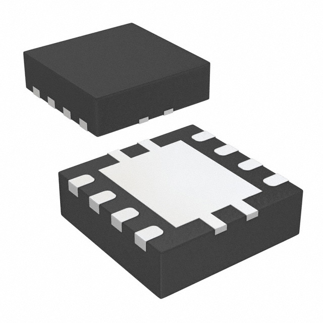
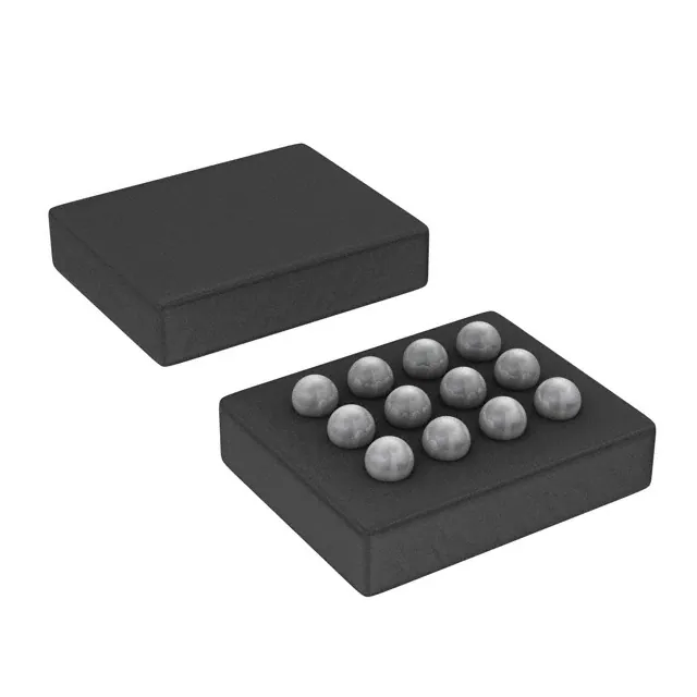
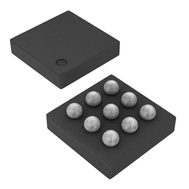
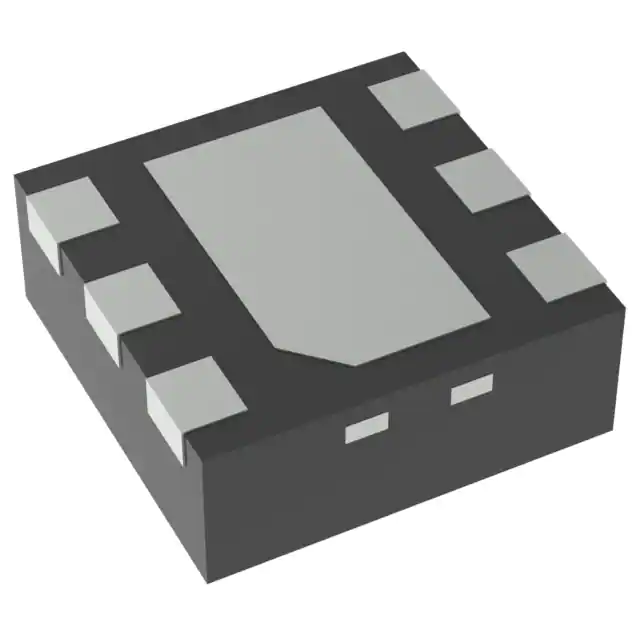
These devices are positive-edge-triggered D-type flip-flops with a common enable input. The ’HCT273 devices are similar to the ’HCT377 devices, but feature a common clear enable (CLR)\ input instead of a latched clock.
Information at the data (D) inputs meeting the setup time requirements is transferred to the Q outputs on the positive-going edge of the clock (CLK) pulse. Clock triggering occurs at a particular voltage level and is not directly related to the positive-going pulse. When CLK is at either the high or low level, the D input has no effect at the output. The circuits are designed to prevent false clocking by transitions at (CLR)\.
Feature
- Operating Voltage Range of 4.5 V to 5.5 V
- Outputs Can Drive Up To 10 LSTTL Loads
- Low Power Consumption, 80-μA Max ICC
- Typical tpd = 12 ns
- ±4-mA Output Drive at 5 V
- Low Input Current of 1 μA Max
- Inputs Are TTL-Voltage Compatible
- Contain Eight D-Type Flip-Flops
- Direct Clear Input
- Applications Include:
- Buffer/Storage Registers
- Shift Registers
- Pattern Generators
These devices are positive-edge-triggered D-type flip-flops with a common enable input. The ’HCT273 devices are similar to the ’HCT377 devices, but feature a common clear enable (CLR)\ input instead of a latched clock.
Information at the data (D) inputs meeting the setup time requirements is transferred to the Q outputs on the positive-going edge of the clock (CLK) pulse. Clock triggering occurs at a particular voltage level and is not directly related to the positive-going pulse. When CLK is at either the high or low level, the D input has no effect at the output. The circuits are designed to prevent false clocking by transitions at (CLR)\.


