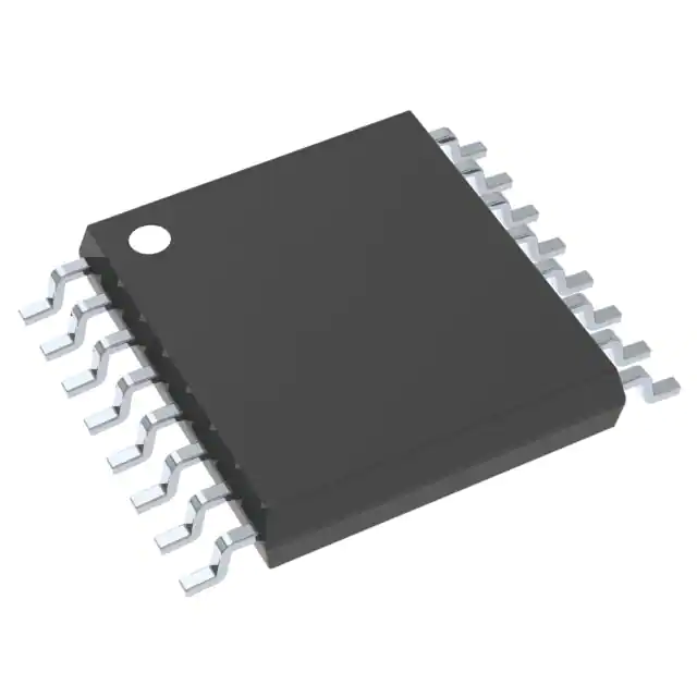
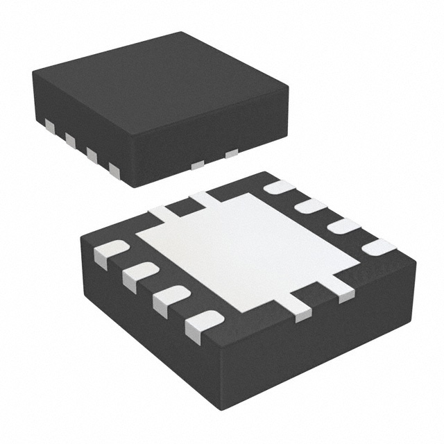
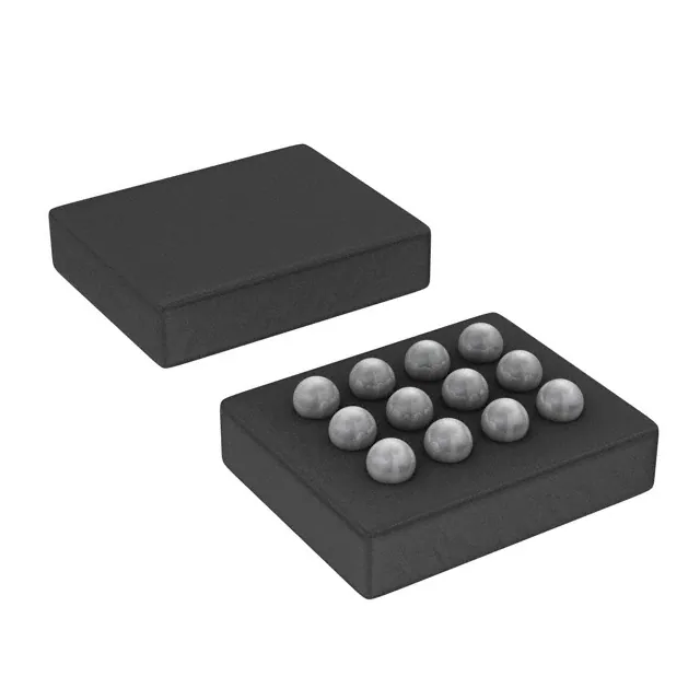
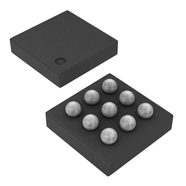
Component qualification in accordance with JEDEC and industry standards to ensure reliable operation over an extended temperature range. This includes, but is not limited to, Highly Accelerated Stress Test (HAST) or biased 85/85, temperature cycle, autoclave or unbiased HAST, electromigration, bond intermetallic life, and mold compound life. Such qualification testing should not be viewed as justifying use of this component beyond specified performance and environmental limits.
DescriptionThe SN74LV123ATPWREP is a dual retriggerable monostable multivibrator designed for 2-V to 5.5-V VCC operation.
This edge-triggered multivibrator features output pulse-duration control by three methods. In the first method, the A\ input is low, and the B input goes high. In the second method, the B input is high, and the A\ input goes low. In the third method, the A\ input is low, the B input is high, and the clear (CLR)\ input goes high.
The output pulse duration is programmable by selecting external resistance and capacitance values. The external timing capacitor must be connected between Cext and Rext/Cext (positive) and an external resistor connected between Rext/Cext and VCC. To obtain variable pulse durations, connect an external variable resistance between Rext/Cext and VCC. The output pulse duration also can be reduced by taking CLR\ low.
Pulse triggering occurs at a particular voltage level and is not directly related to the transition time of the input pulse. The A\, B, and CLR\ inputs have Schmitt triggers with sufficient hysteresis to handle slow input transition rates with jitter-free triggering at the outputs.
Once triggered, the basic pulse duration can be extended by retriggering the gated low-level-active (A)\ or high-level-active (B) input. Pulse duration can be reduced by taking CLR\ low. The input/output timing diagram illustrates pulse control by retriggering the inputs and early clearing.
During power up, Q outputs are in the low state, and Q\ outputs are in the high state. The outputs are glitch free, without applying a reset pulse.
This device is fully specified for partial-power-down applications using Ioff. The Ioff circuitry disables the outputs, preventing damaging current backflow through the device when it is powered down.
Feature
- Controlled Baseline
- One Assembly/Test Site, One Fabrication Site
- Extended Temperature Performance of –40°C to 105°C
- Enhanced Diminishing Manufacturing Sources (DMS) Support
- Enhanced Product-Change Notification
- Qualification Pedigree
- Typical VOLP (Output Ground Bounce) <0.8 V at VCC = 3.3 V, TA = 25°C
- Typical VOHV (Output VOH Undershoot) >2.3 V at VCC = 3.3 V, TA = 25°C
- Supports Mixed-Mode Voltage Operation on All Ports
- Schmitt-Trigger Circuitry on A\, B, and CLR\ Inputs for Slow Input Transition Rates
- Edge Triggered From Active-High or Active-Low Gated Logic Inputs
- Ioff Supports Partial-Power-Down Mode Operation
- Retriggerable for Very Long Output Pulses, Up To 100% Duty Cycle
- Overriding Clear Terminates Output Pulse
- Glitch-Free Power-Up Reset on Outputs
- ESD Protection Exceeds JESD 22
- 2000-V Human-Body Model (A114-A)
- 200-V Machine Model (A115-A)
- 1000-V Charged-Device Model (C101)
Component qualification in accordance with JEDEC and industry standards to ensure reliable operation over an extended temperature range. This includes, but is not limited to, Highly Accelerated Stress Test (HAST) or biased 85/85, temperature cycle, autoclave or unbiased HAST, electromigration, bond intermetallic life, and mold compound life. Such qualification testing should not be viewed as justifying use of this component beyond specified performance and environmental limits.
DescriptionThe SN74LV123A is a dual retriggerable monostable multivibrator designed for 2-V to 5.5-V VCC operation.
This edge-triggered multivibrator features output pulse-duration control by three methods. In the first method, the A\ input is low, and the B input goes high. In the second method, the B input is high, and the A\ input goes low. In the third method, the A\ input is low, the B input is high, and the clear (CLR)\ input goes high.
The output pulse duration is programmable by selecting external resistance and capacitance values. The external timing capacitor must be connected between Cext and Rext/Cext (positive) and an external resistor connected between Rext/Cext and VCC. To obtain variable pulse durations, connect an external variable resistance between Rext/Cext and VCC. The output pulse duration also can be reduced by taking CLR\ low.
Pulse triggering occurs at a particular voltage level and is not directly related to the transition time of the input pulse. The A\, B, and CLR\ inputs have Schmitt triggers with sufficient hysteresis to handle slow input transition rates with jitter-free triggering at the outputs.
Once triggered, the basic pulse duration can be extended by retriggering the gated low-level-active (A)\ or high-level-active (B) input. Pulse duration can be reduced by taking CLR\ low. The input/output timing diagram illustrates pulse control by retriggering the inputs and early clearing.
During power up, Q outputs are in the low state, and Q\ outputs are in the high state. The outputs are glitch free, without applying a reset pulse.
This device is fully specified for partial-power-down applications using Ioff. The Ioff circuitry disables the outputs, preventing damaging current backflow through the device when it is powered down.

