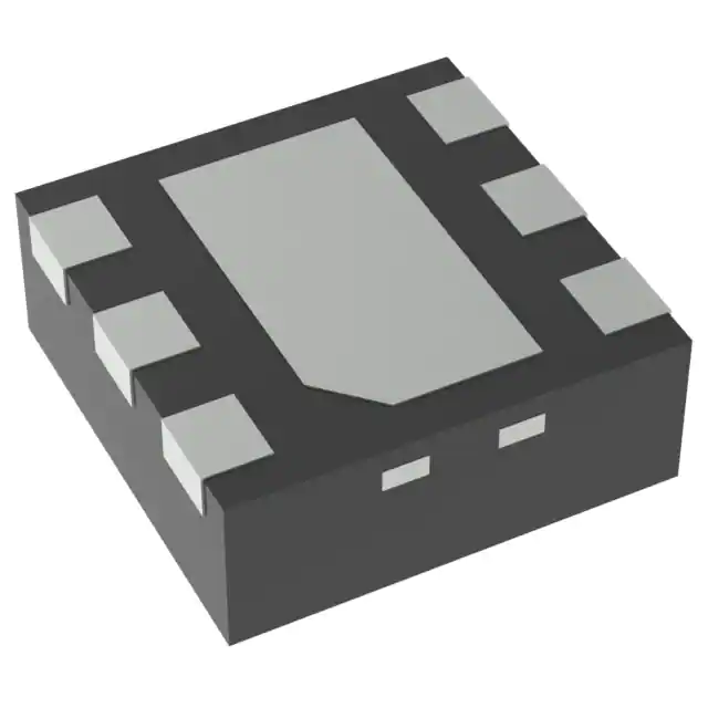
These edge-triggered multivibrators feature output pulse-duration control by three methods. In the first method, the A\ input is low, and the B input goes high. In the second method, the B input is high, and the A\ input goes low. In the third method, the A\ input is low, the B input is high, and the clear (CLR)\ input goes high.
The output pulse duration is programmed by selecting external resistance and capacitance values. The external timing capacitor must be connected between Cext and Rext/Cext (positive) and an external resistor connected between Rext/Cext and VCC. To obtain variable pulse durations, connect an external variable resistance between Rext/Cext and VCC. The output pulse duration also can be reduced by taking CLR\ low.
Pulse triggering occurs at a particular voltage level and is not directly related to the transition time of the input pulse. The A\, B, and CLR\ inputs have Schmitt triggers with sufficient hysteresis to handle slow input transition rates with jitter-free triggering at the outputs.
Once triggered, the basic pulse duration can be extended by retriggering the gated low-level-active (A\) or high-level-active (B) input. Pulse duration can be reduced by taking CLR\ low. CLR\ input can be used to override A\ or B inputs. The input/output timing diagram illustrates pulse control by retriggering the inputs and early clearing.
The variance in output pulse duration from device to device typically is less than ±0.5% for given external timing components. An example of this distribution for the ’AHCT123A is shown in Figure 10. Variations in output pulse duration versus supply voltage and temperature are shown in Figure 6.
During power up, Q outputs are in the low state, and Q\ outputs are in the high state. The outputs are glitch free, without applying a reset pulse.
For additional application information on multivibrators, see the application report, Designing With the SN74AHC123A and SN74AHCT123A, literature number SCLA014.
Feature
- Inputs Are TTL-Voltage Compatible
- Schmitt-Trigger Circuitry On A\, B, and CLR\ Inputs for Slow Input Transition Rates
- Edge Triggered From Active-High or Active-Low Gated Logic Inputs
- Retriggerable for Very Long Output Pulses
- Overriding Clear Terminates Output Pulse
- Latch-Up Performance Exceeds 100 mA Per JESD 78, Class II
- ESD Protection Exceeds JESD 22
- 2000-V Human-Body Model (A114-A)
- 200-V Machine Model (A115-A)
- 1000-V Charged-Device Model (C101)
These edge-triggered multivibrators feature output pulse-duration control by three methods. In the first method, the A\ input is low, and the B input goes high. In the second method, the B input is high, and the A\ input goes low. In the third method, the A\ input is low, the B input is high, and the clear (CLR)\ input goes high.
The output pulse duration is programmed by selecting external resistance and capacitance values. The external timing capacitor must be connected between Cext and Rext/Cext (positive) and an external resistor connected between Rext/Cext and VCC. To obtain variable pulse durations, connect an external variable resistance between Rext/Cext and VCC. The output pulse duration also can be reduced by taking CLR\ low.
Pulse triggering occurs at a particular voltage level and is not directly related to the transition time of the input pulse. The A\, B, and CLR\ inputs have Schmitt triggers with sufficient hysteresis to handle slow input transition rates with jitter-free triggering at the outputs.
Once triggered, the basic pulse duration can be extended by retriggering the gated low-level-active (A\) or high-level-active (B) input. Pulse duration can be reduced by taking CLR\ low. CLR\ input can be used to override A\ or B inputs. The input/output timing diagram illustrates pulse control by retriggering the inputs and early clearing.
The variance in output pulse duration from device to device typically is less than ±0.5% for given external timing components. An example of this distribution for the ’AHCT123A is shown in Figure 10. Variations in output pulse duration versus supply voltage and temperature are shown in Figure 6.
During power up, Q outputs are in the low state, and Q\ outputs are in the high state. The outputs are glitch free, without applying a reset pulse.
For additional application information on multivibrators, see the application report, Designing With the SN74AHC123A and SN74AHCT123A, literature number SCLA014.

